A rooftop solar power plant is an integrated photovoltaic electricity-generation system installed on a building roof rather than simply a collection of solar panels. Its core components include photovoltaic (PV) modules to generate Direct Current (DC), an engineered mounting structure, UV-rated DC cables and connectors, a DC Distribution Box (DCDB) for isolation and surge suppression, a solar inverter to convert DC into grid-synchronized Alternating Current (AC), an AC Distribution Box (ACDB), dedicated earthing and lightning protection, a bidirectional net meter, and an IoT monitoring system, with optional battery storage added where emergency backup or off-grid autonomy is required.
What Are the Main Components of a Rooftop Solar System?
Before examining the physics, electrical design parameters, and engineering selection criteria for individual devices, review this consolidated reference table outlining the twelve essential subsystems of a modern rooftop solar installation.
| Component | Primary Function | Electrical / Mechanical Role | Typical Installation Location |
|---|---|---|---|
| Solar PV Modules | Convert sunlight into DC electricity | Photovoltaic energy generation | Rooftop (RCC slab, metal sheet, or elevated truss) |
| Mounting Structure | Supports and positions PV modules | Mechanical stability, tilt & azimuth orientation | Anchored or ballasted directly onto roof substructure |
| DC Cables & Connectors | Carry DC electricity | Low-loss, UV-resistant conductor routing (MC4) | Underneath module rails and inside UV conduits |
| DCDB / Combiner Equipment | DC protection and isolation where applicable | Overcurrent string fuses, DC isolator switch, DC SPD | Near PV array or adjacent to string inverter |
| Solar Inverter | Converts DC electricity into AC electricity | MPPT optimization, DC-to-AC conversion, grid sync | Wall-mounted in shaded, ventilated technical area |
| ACDB | AC protection and distribution | Overcurrent circuit breaker (MCB/MCCB), AC SPD | Adjacent to inverter or near building main panel |
| AC Cables | Carry AC electricity | Armored/conduit cabling linking inverter to LT panel | Electrical conduit run between inverter & panel |
| Earthing System | Provides electrical safety and bonding | Fault-current discharge, equipment bonding pits | Soil pits on ground or designated building earth busbar |
| Lightning & Surge Protection | Protects equipment from electrical transients | Direct strike mitigation (arrester) & transient SPDs | Elevated rooftop air terminal & distribution boxes |
| Metering System | Measures electricity import/export | Bidirectional recording for DISCOM net metering | Utility consumer meter board / service point |
| Monitoring System | Tracks generation and performance | IoT data logging, cloud analytics, fault alerts | Inverter communication port (Wi-Fi/LAN/4G dongle) |
| Battery Storage (Optional) | Stores energy for backup/autonomy | Chemical energy storage in hybrid/off-grid setups | Well-ventilated utility room or dedicated battery rack |
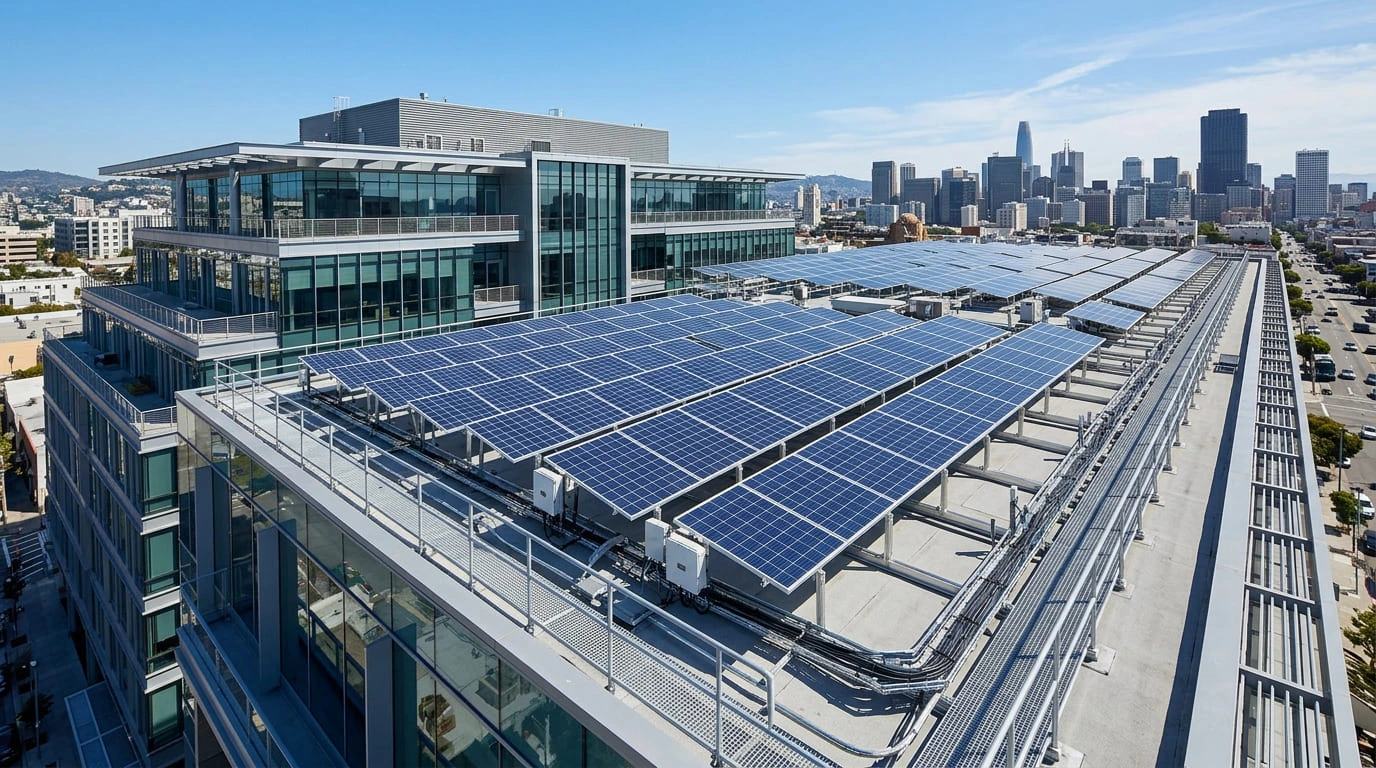
Technical System Architecture & Power Flow
A rooftop solar power plant operates through a continuous, closed-loop electro-mechanical sequence. Understanding the physical journey of power—from photon absorption to household appliance consumption and utility grid export—is fundamental for engineering students, technicians, and system owners alike.
System Energy Flow Architecture
Energy Flow: PV Modules → DCDB → String Inverter → ACDB → Building Loads ↔ Net Meter & Utility GridHow Does a Rooftop Solar Power Plant Work?
The generation of electrical energy from a rooftop solar power plant follows ten coordinated stages, moving from atmospheric light absorption through solid-state physics to municipal utility synchronization:
Sunlight Reaches PV Modules
Solar irradiance (photons) strikes the anti-reflective glass surface of rooftop photovoltaic modules at an engineered angle of inclination.
Photovoltaic Effect Occurs
Photons with energy greater than the silicon bandgap (1.1 eV) knock electrons free from valence shells within the p-n junction, establishing an electric field.
Strings Form High DC Voltages
Individual solar cells (each generating approx. 0.5–0.6V) are connected in series inside modules, and modules are interconnected in series strings to achieve optimal operating voltage (typically 300V–800V DC).
DC Cables Channel Current
Double-insulated, UV-stabilized, halogen-free cross-linked polyolefin (XLPO) solar DC cables conduct the direct current toward the power conditioning unit.
DC Protection Shields the System
String fuses (gPV rated), DC surge protection devices (SPDs), and a certified rotary DC isolator switch provide overcurrent, transient, and maintenance protection.
Inverter Converts DC to AC
High-speed Maximum Power Point Tracking (MPPT) microprocessors optimize array yield, while insulated gate bipolar transistors (IGBTs) invert direct current into clean 230V single-phase or 415V three-phase alternating current.
ACDB Regulates Power Delivery
The Alternating Current Distribution Box utilizes miniature circuit breakers (MCBs) or molded case circuit breakers (MCCBs) and Type 2 AC SPDs to protect building circuits.
Self-Consumption Powers Local Loads
In accordance with Kirchhoff’s Current Law, generated electrons flow to the nearest electrical loads (appliances, machinery, HVAC systems) reducing grid consumption to zero.
Bidirectional Meter Logs Net Flow
Surplus energy that exceeds building demand flows out through the utility meter to the distribution company (DISCOM) grid, earning monetary or billing energy credits.
IoT Monitoring Diagnoses Performance
Digital sensors and communication dongles log kilowatt-hour generation, string voltages, ambient temperature, and clipping losses to cloud servers for remote O&M tracking.
Want to master solar PV system design, calculation, and EPC commissioning?
Explore the industry-recognized curriculum developed by senior renewable-energy practitioners at the Indian Institute of Solar Energy. Learn string sizing, PVSyst simulation, electrical drawings, and plant safety standards.
1. Solar PV Modules: The Primary Energy Generators
Solar panels are the dark, rectangular sheets visible on rooftops. When sunlight shines on them, the materials inside automatically create electricity. They have no moving parts, create no noise or smoke, and require only occasional cleaning with clean water to produce energy for 25 to 30 years.
Photovoltaic modules are hermetically encapsulated matrices of crystalline silicon semiconductor cells connected in series-parallel configurations. Under photon bombardment, valence electrons are excited into conduction bands across the p-n junction. Modules are rated at Standard Test Conditions (STC: 1000 W/m² irradiance, 25°C cell temperature, AM 1.5G spectrum).
Key Technical Specifications to Analyze on Datasheets
When conducting solar design and component evaluation, never evaluate modules purely on their peak nameplate wattage ($W_p$). Always inspect the electrical nameplate parameters:
Solar Cell Technology Comparison
- Monocrystalline PERC: High efficiency (20.5%–21.5%), established reliability, single-crystal silicon structure.
- N-Type TOPCon (Tunnel Oxide Passivated Contact): Market leading efficiency (22%–23.5%), lower degradation, superior performance in diffuse morning/evening light, and lower temperature coefficient.
- Bifacial Glass-Glass Modules: Features transparent backsheets or dual-glass construction that captures reflected sunlight (albedo) from rooftop white coatings or RCC slabs, generating 5%–15% bonus energy.
How Many Solar Panels Are Needed for a Rooftop Solar System?
The number of modules required is not universal; it is determined by the required kilowatt ($kW$) capacity divided by the individual module power rating ($W_p$), constrained by available shadow-free roof area.
• Desired Generation Capacity: 5.0 kW (5,000 Watts DC)
• Selected Module Specification: 550 Wp N-Type Mono TOPCon
• Module Quantity Formula: 5,000 W / 550 Wp = 9.09 modules → 10 Modules (Total DC capacity: 5,500 Wp / 5.5 kWp)
• Physical Area Required: 10 modules × ~2.6 m² per module ≈ 26 m² (~280 sq. ft) of shadow-free rooftop space.
• Estimated Energy Output: 5.5 kWp × 4.0 Peak Sun Hours (PSH) × 0.78 (Performance Ratio) ≈ 17.1 to 21 kWh (units) per day.
Note: Calculations vary based on geographic location, seasonal tilt optimization, shading obstructions, and seasonal dust accumulation. Learn complete string sizing in our solar calculation modules.
2. Solar Module Mounting Structure (MMS): Structural Integrity
The solar module mounting structure (MMS) provides the structural foundation of the rooftop power plant. It mechanically anchors the modules to the building substrate, fixes the orientation and tilt angle to maximize solar irradiance capture, and resists structural dead loads, live loads, and extreme lateral wind uplifts throughout a 25-year lifespan.
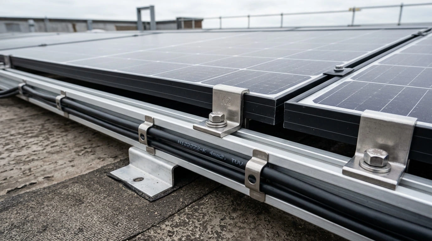
Comparison of Roof Types and Mounting Methodologies
| Roof Type | Mounting Architecture | Main Structural Consideration | Fastening & Waterproofing Protocol |
|---|---|---|---|
| Flat RCC Roof (Reinforced Concrete) | Triangular ballasted or anchor-bolted leg frames | Dead-weight capacity of roof slab; preserving waterproofing membrane | Anchor fasteners grouted with non-shrink chemical resin, or non-penetrating precast concrete ballast blocks with EPDM vibration dampers. |
| Trapezoidal Metal Sheet (Tin Shed) | Mini-rail or short-rail system mounted on sheet crowns | Sheet gauge thickness (minimum 0.5mm recommended); purlin load capacity | Self-drilling screws with EPDM sealing washers; rivets fixed directly into structural purlins where wind speeds exceed 150 km/h. |
| Standing Seam Metal Roof | Non-penetrating seam clamps | Zero roof penetration; thermal expansion of metal sheets | Patented standing seam clamps torque-calibrated directly onto the folded seam without puncturing sheet weatherproofing. |
| Tiled / Slanted Roof (Clay / Mangalore) | Rooftop tile hooks under-rafter bolted | Fragility of ceramic tiles; structural wood/steel rafter alignment | Stainless steel tile brackets fastened directly into rafters beneath tiles; tiles re-seated with flexible flashing mastic. |
Key Engineering Specifications for Mounting Systems
- Structural Materials: Hot-Dip Galvanized Iron (HDGI with minimum 80-micron zinc coating per IS 4759) or extruded Anodized Aluminium (6063-T6 grade with minimum 15-micron anodization).
- Fasteners: Stainless Steel Grade SS304 or marine-grade SS316. Dissimilar metals (e.g. aluminium against zinc-plated carbon steel) must be electrically isolated using nylon/EPDM washers to eliminate galvanic corrosion.
- Wind Loading Compliance: Structural framing and foundation ballasting must be certified by a structural engineer in accordance with IS 875 (Part 3) to withstand regional wind velocities (up to 150–200 km/h in coastal/cyclone zones).
- Tilt and Azimuth Optimization: In India (Northern Hemisphere), arrays face true South (Azimuth 180°). Optimal fixed tilt angle typically corresponds approximately to the site’s geographic latitude (e.g., 18°–20° in Mumbai/Pune, 28° in New Delhi) to optimize annual yield while ensuring self-cleaning water runoff.
3. Solar DC Cables & MC4 Connectors: The High-Voltage Conductor Route
Solar arrays operate at high DC voltages (up to 1000V or 1500V DC). Because DC arcs do not cross a zero-voltage threshold like alternating current, DC cabling and contact points represent one of the highest fire and safety risks in photovoltaic installations if improperly specified or crimped.
- Cross-Mating Incompatible Connectors: Mating genuine Stäubli MC4 connectors with generic clones. Microscopic dimensional tolerances differ, leading to contact resistance, thermal runaway, and electrical fires.
- Undersized Cable Gauge: Designing strings with 2.5 mm² instead of 4 mm² or 6 mm², causing unacceptable resistive voltage drops (> 1.5%) and overheating.
- Improper Hand-Crimping: Using generic pliers instead of calibrated ratcheting MC4 crimp tools with correct die sets, causing loose contact resistance.
- Exposed Cables Lying on Roof: Leaving DC cables unclipped on wet concrete slabs where water puddles degrade insulation over time. All cables must be bundled inside UV-resistant conduit pipes or clipped along mounting rails.
4. DCDB (DC Distribution Box) & DC Protection Architecture
The Direct Current Distribution Box (DCDB) provides array-side isolation, string overcurrent protection, and transient surge suppression before DC energy reaches the inverter inputs.
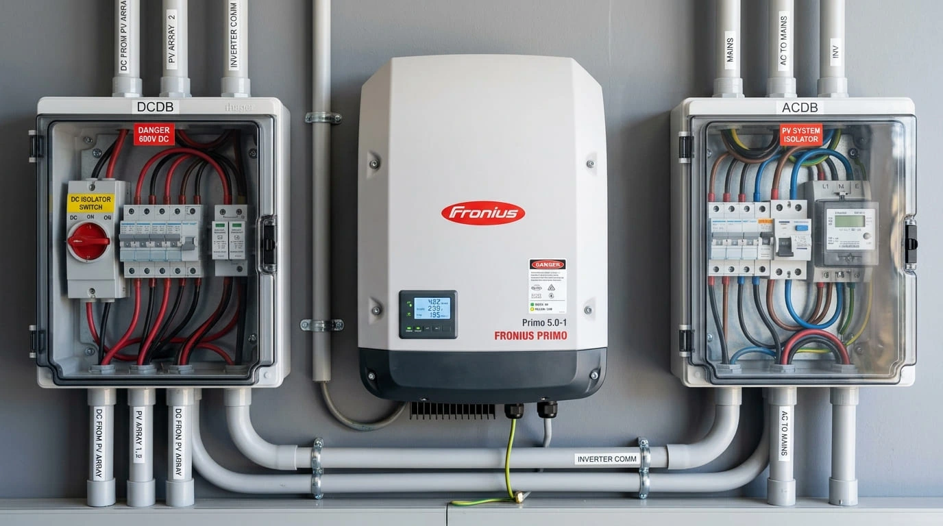
Core Components Inside a Standard DCDB
- DC Isolator Switch (IEC 60947-3): Load break switch capable of safely interrupting direct current under full array voltage (up to 1000V DC) for maintenance isolation.
- gPV String Fuses (IEC 60269-6): Fast-acting photovoltaic fuses rated for DC overcurrent protection. Essential in parallel strings to prevent reverse backfeed currents from healthy strings into a faulted string.
- DC Surge Protection Device (SPD Type 2): Metal Oxide Varistor (MOV) arresters designed according to EN 50539-11 / IEC 61643-31 that clamp high-voltage lightning surges and divert them to the earth pit.
- Polycarbonate / FRP Enclosure: Ingress protection rating of IP65 or IP66, UV-stabilized, impact-resistant, with waterproof cable glands.
5. Solar Inverter: The Brain and Power Conversion Core
The solar inverter is the primary active electrical component in a rooftop power plant. While solar panels produce fluctuating direct current (DC), consumer building circuits and the national utility grid operate exclusively on alternating current (AC) at 50 Hz frequency.
Think of the inverter as a universal power translator. Sunlight makes DC power (like power in a battery), but TV, fans, air conditioners, and the power company use AC electricity. The inverter transforms this raw power into smooth AC electricity that matches your building's supply.
The inverter utilizes high-frequency Insulated Gate Bipolar Transistor (IGBT) H-bridges to perform DC-to-AC power inversion with total harmonic distortion (THD < 3%). It runs continuous Maximum Power Point Tracking (MPPT) perturb-and-observe or incremental-conductance algorithms to match dynamic array impedance, while phase-locked loops (PLL) synchronize output voltage, frequency, and phase angle with the grid.
Comparison of Inverter Architectures
| Inverter Type | Suitable Application | Key Advantages | Engineering Limitations |
|---|---|---|---|
| String Inverter | Standard residential, commercial & industrial rooftops | Cost-effective, highly reliable, centralized indoor/outdoor maintenance, 98%+ efficiency. | String-level output is throttled if individual panels experience partial shading or mismatch. |
| Microinverter | Complex multi-orientation roofs, heavy partial shading | Module-level MPPT (MLPE), zero high-voltage DC on roof, plug-and-play expansion. | Higher initial capital cost per watt; multiple electronic units situated in harsh rooftop thermal environments. |
| Hybrid Inverter | Homes & businesses requiring battery energy storage | Seamless grid-tied operation with integrated battery bidirectional charger and islanding backup. | More complex system wiring, higher equipment expense, requires battery storage engineering. |
| Central Inverter | Very large industrial rooftops & utility solar parks (> 1 MW) | Consolidated high-power capacity in a single containerized station, low per-watt equipment cost. | Single point of failure; extensive long DC cable runs required; completely unsuitable for small rooftops. |
Essential Safety Functions: Anti-Islanding Protection
Under international standards (IEEE 1547 / IEC 62116) and Central Electricity Authority (CEA) regulations, grid-tied inverters must possess automatic anti-islanding protection. If the municipal grid loses power due to a blackout or line fault, the inverter must disconnect within milliseconds (typically < 100 ms). This prevents the solar plant from energizing local utility power lines, protecting electrical line workers from lethal electric shocks.
6. ACDB (AC Distribution Box): Inverter-to-Grid Protection
The Alternating Current Distribution Box (ACDB) receives the inverted AC power from the solar inverter and provides circuit isolation, overcurrent protection, and surge suppression before connecting to the building's main low-tension (LT) distribution board.
ACDB vs DCDB: A Functional Side-by-Side Comparison
| Evaluation Criteria | DCDB (DC Distribution Box) | ACDB (AC Distribution Box) |
|---|---|---|
| Circuit Location | Between Solar PV Array and Inverter Input | Between Inverter AC Output and Building LT Panel |
| Current Type | Direct Current (DC) | Alternating Current (AC) - 50 Hz |
| Operating Voltage | 300V to 1000V DC | 230V Single Phase / 415V Three Phase AC |
| Protective Switchgear | Rotary DC Isolator + gPV DC Fuses | AC MCB (Miniature) / MCCB (Molded Case) + RCD |
| Surge Arresters (SPD) | Type 2 DC SPD (IEC 61643-31) | Type 2 AC SPD (IEC 61643-11) |
| Arc Quenching | Requires magnetic arc blowouts or wide contact gaps | Natural arc quenching occurs during zero-voltage AC crossings |
7. Solar AC Cabling: Sizing & Distribution
AC cables carry alternating current from the inverter output to the ACDB, and onward to the main electrical panel. Proper selection of AC cable sizing is vital to minimize power transmission losses, prevent overheating, and ensure that the voltage rise remains within the operational window of the inverter.
- Conductor Material: Copper (flexible stranded Class 2/Class 5) or Aluminium (Class 2 stranded armored XLPE cables). Copper is standard for residential systems; multi-core armored aluminium cables (AYFY / XLPE) are standard for commercial multi-kilowatt runs.
- Permissible Voltage Drop: In solar engineering design, total AC voltage drop from the inverter terminals to the main utility injection point must not exceed 2.0% (and ideally < 1.0%). Excessive resistance causes voltage rise at the inverter terminals, triggering nuisance inverter over-voltage shutdowns on hot, high-generation afternoons.
- Mechanical Protection: Armored cables with galvanized steel wire/strip armor are utilized for outdoor/underground routes; non-armored cables must be protected within rigid metallic or UV-stabilized PVC conduits.
Build practical solar industry skills with real rooftop plant commissioning
Master component selection, DC/AC distribution assembly, inverter parameter programming, and DISCOM net-metering liaison in our comprehensive certification programs.
8. Earthing and Grounding System: Personnel and Asset Safety
Earthing provides a low-resistance path to discharge electrical fault currents safely into the ground, protects human life from electric shocks, prevents equipment damage, and maintains equipotential bonding across module frames and structures.
The Three Dedicated Earthing Circuits in Rooftop Solar
A properly engineered rooftop solar power plant in India does not combine all grounding connections into a single point. Industry best practices specify three distinct earthing pits:
- DC Array & Structure Earthing: Bonds all anodized aluminium module frames together using serrated grounding washers/clips, connecting directly to the mounting structure rails, and routing down to a dedicated earth pit.
- Inverter & ACDB Enclosure Earthing: Connects the metallic bodies of the inverter, ACDB chassis, and LT electrical switchgear to an independent equipment earth pit to ensure immediate circuit breaker tripping during insulation failure.
- Dedicated Lightning Protection Earthing: Directly grounds the external rooftop lightning arrester via an insulated down conductor to its own low-impedance earth electrode pit.
9. Lightning Protection & Surge Protection Devices (SPDs)
Rooftop solar arrays increase a building's metallic surface area, making comprehensive lightning and transient protection essential. A complete protection strategy combines external lightning protection (LPS) with internal surge suppression.
- External Lightning Air Terminal: Rooftop air terminal (Franklin rod or Early Streamer Emission - ESE terminal) engineered in accordance with IS/IEC 62305 using the Rolling Sphere method to create a protective cone covering all solar modules.
- Dedicated Down Conductor: Continuous, heavy-gauge conductor (minimum 25x3 mm copper or GI strip) routed along the building exterior directly to the earth pit with zero sharp 90-degree bends.
- Internal Surge Protection Devices (SPDs): Coordinated Type 1 (direct lightning discharge) and Type 2 (induced switching and transient overvoltage) SPDs installed inside the DCDB and ACDB to prevent voltage spikes from puncturing inverter semiconductor junctions.
10. Solar Metering & Grid Connection (India Context)
In a grid-connected rooftop solar power plant, the metering equipment measures electrical energy flow between your building and the electrical utility company (DISCOM).
Bidirectional Net Meter vs Gross Meter
- Bidirectional Net Meter (Net Metering): A dual-register energy meter that records energy imported from the grid when consumption exceeds solar production, and registers energy exported to the grid when solar generation exceeds local building demand. The consumer is billed only for the net difference ($kWh_{imported} - kWh_{exported}$).
- Gross Metering: All solar power produced is exported directly to the grid through a dedicated export meter at a fixed feed-in tariff (FIT), while all building consumption is imported and billed separately at standard retail tariffs.
- Solar Generation Meter: A check meter installed at the inverter AC output that measures total gross solar energy generated by the system, often utilized for renewable energy certificate (REC) calculations or state generation-based incentives (GBI).
11. Solar Monitoring System: IoT Diagnostics & Yield Tracking
A solar power plant is an active financial asset. Without digital monitoring, performance degradation caused by module dust accumulation, localized shading, string fuse blowouts, or inverter grid-voltage trip events can go unnoticed for weeks, resulting in substantial financial loss.
Modern Monitoring System Architecture
- Hardware Interface: Communication dongle (Wi-Fi, 4G LTE cellular SIM, or wired Ethernet LAN) plugged into the inverter's RS485 / Modbus port.
- Real-Time Yield Metrics: Instantaneous generation (kW), cumulative daily energy (kWh), lifetime energy generation (MWh), and grid voltage/frequency.
- Fault Alerts: Immediate mobile push notifications and email alerts triggered by ground faults, grid loss, high ambient temperature, or string isolation errors.
- O&M Diagnostics: String-level MPPT current comparison allows maintenance technicians to identify dirty panels, PID degradation, or micro-cracks from an office dashboard without climbing the roof.
12. Battery Storage: Is a Battery Required for Rooftop Solar?
No. A battery is not automatically required for a standard grid-connected (on-grid) rooftop solar power plant.
Over 90% of urban residential and commercial solar installations in India are standard on-grid systems without batteries. The public electrical grid acts as a virtual battery: excess solar electricity is sent to the grid during the afternoon, and grid electricity is imported at night.
Battery Chemistry Comparison (When Storage Is Desired)
| Battery Technology | Usable Depth of Discharge (DoD) | Cycle Life | Efficiency & Footprint | Best Suited Application |
|---|---|---|---|---|
| Lithium Iron Phosphate (LiFePO4) | 80% – 90% DoD | 4,000 to 6,000+ cycles | High round-trip efficiency (> 95%), compact, wall-mountable, built-in smart BMS. | Modern residential & commercial hybrid solar setups requiring clean daily cycling. |
| Tubular Lead-Acid | 50% DoD | 1,200 to 1,800 cycles | Moderate efficiency (~75%–80%), heavy, requires distilled water maintenance, off-gases hydrogen. | Budget off-grid agricultural solar installations with infrequent cycle requirements. |
13. What Is Balance of System (BoS) in Rooftop Solar?
In solar engineering terminology, Balance of System (BoS) encompasses all components and subsystems of a photovoltaic power plant other than the solar PV modules themselves.
While the photovoltaic modules generate raw DC electricity, the BoS is what allows the energy to be securely mounted, safely conducted, converted into usable AC power, protected against electrical faults, metered, and synchronized with building loads and the utility grid.
14. Complete Rooftop Solar Component Checklist
Use this visual checklist to review every physical subsystem of a commercial or residential rooftop installation during EPC engineering audits or site handover:
15. Component Requirement Matrix
Not every solar component is mandated across all project configurations. Use this matrix to discern between universally mandatory core components and architecture-dependent equipment:
| Component | Requirement Level | Primary Function | Typical Location |
|---|---|---|---|
| PV Module | Core Component | Generates DC electricity from sunlight | Rooftop surface |
| Mounting Structure | Core Component | Mechanically secures & orients modules | Anchored to rooftop slab/shed |
| Solar Inverter | Core Component | Converts DC power into grid-ready AC | Shaded plant equipment wall |
| DC Protection / DCDB | Design Dependent | DC isolation, string fusing, surge suppression | Array vicinity or inside inverter |
| ACDB | Design Dependent | AC circuit protection and isolation | Adjacent to inverter / main panel |
| DC Solar Cables | Core Component | Transmits direct current from modules | Module rails & UV conduits |
| AC Power Cables | Core Component | Transmits AC electricity to building loads | Cable trays & electrical riser runs |
| Earthing System | Mandatory Safety | Personnel protection & fault drainage | Ground earth pits & structure frames |
| Lightning Arrester | Site Dependent | Direct atmospheric strike mitigation | Elevated mast on highest roof point |
| Bidirectional Meter | Grid Dependent | Records energy export and import for net billing | DISCOM utility meter cabin |
| Monitoring Unit | Strongly Recommended | Cloud logging, yield tracking, fault alerts | Integrated inverter communication port |
| Battery Storage | Optional | Stores energy for power outages/autonomy | Battery room / indoor rack enclosure |
16. Which Components Change Between On-Grid, Hybrid, and Off-Grid Solar?
System architecture dictates which components are required, how safety circuits are routed, and what happens when the municipal grid fails:
| Component / Feature | On-Grid (Grid-Tied) | Hybrid (Solar + Storage) | Off-Grid (Autonomous) |
|---|---|---|---|
| Solar PV Modules | Yes (Standard Array) | Yes (Standard Array) | Yes (Standard Array) |
| Inverter Architecture | Grid-Tied String or Microinverter | Hybrid Bi-Directional Inverter | Off-Grid Inverter + Charge Controller |
| Mounting Structure | Yes | Yes | Yes |
| DC Protection / DCDB | Design Dependent | Design Dependent | Design Dependent |
| AC Protection (ACDB) | Yes (Standard Breaker) | Yes (Dual Grid & Backup Outputs) | System Dependent |
| Grid Interconnection | Yes (Mandatory) | Usually Connected | No (Fully Isolated) |
| Bidirectional Net Meter | Yes (Where DISCOM allows) | Yes (Where DISCOM allows) | No (Not Connected to Grid) |
| Battery Bank (BESS) | Usually Not Required | Yes (Mandatory for Hybrid) | Yes (Mandatory for Off-Grid) |
| Charge Controller | Not Applicable (Inverter MPPT) | Integrated in Hybrid Inverter | Dedicated MPPT Controller / Integrated |
| Power During Grid Outage | Shut Down Automatically (Anti-islanding safety) | Yes (Supplies critical backup panel within milliseconds) | Yes (Completely independent of grid status) |
Important Note: A standard on-grid solar plant will never power your appliances during a daytime power cut unless you install a specialized hybrid inverter with a compatible battery storage bank.
17. How to Choose the Right Rooftop Solar Components
Selecting equipment for a rooftop solar power plant requires balancing electrical engineering compatibility, physical roof constraints, environmental climate conditions, and long-term warranties:
- Energy Consumption & Capacity Matching: Review the past 12 months of utility electricity bills to identify average monthly kilowatt-hour consumption. As a general benchmark in India, 1 kW of rooftop solar generates approximately 1,200 to 1,450 kWh annually.
- Roof Space & Shading Analysis: Conduct a 3D solar shade assessment (using software such as PVSyst or HelioScope). If chimneys, parapet walls, or adjacent high-rises cause localized shading, consider microinverters or multiple independent MPPT trackers.
- Structural Roof Assessment: Confirm whether the roof slab or metal purlins can handle structural dead loads (approx. 15–20 kg/m²) and wind uplift without exceeding deflection limits.
- Climate & Environmental Factors: In coastal environments (e.g. Mumbai, Chennai), specify marine-grade anodized aluminium structures (min. 15 microns) and SS316 fasteners with IP66 enclosures. In high-heat central/northern regions, prioritize modules with superior temperature coefficients (≤ -0.30%/°C).
- Warranties and Manufacturer Bankability: Require a minimum 12-year product warranty and 25 to 30-year linear performance warranty on solar modules (ensuring ≥ 84%–87% generation at Year 25/30), and a minimum 5 to 10-year standard warranty on inverters with local Indian service centres.
18. Common Rooftop Solar Selection and Installation Mistakes
- Selecting Panels Purely on Peak Wattage ($W_p$): Overlooking temperature coefficients, degradation rates, and physical module dimensions.
- Undersized Solar DC Cables: Creating excessive voltage drops and fire hazards by using thin conductors for long rooftop runs.
- Cross-Mating Unmatched MC4 Connectors: Intermating different connector brands, leading to localized heating and arcing.
- Inappropriate Inverter MPPT Voltage Matching: Designing strings with open-circuit voltages ($V_{oc}$) that exceed the inverter's maximum DC input under winter cold temperatures.
- Omitting Dedicated Earthing Pits: Connecting solar equipment to existing household earth wires rather than installing dedicated chemical earth pits.
- Combining Lightning and Array Earthing: Blending the lightning arrester down conductor with solar module frames.
- Ignoring Structural Roof Fastener Sealing: Drilling into RCC slabs without polyurethane/chemical waterproofing, causing water leaks.
- Disregarding Local Shading: Installing panels directly behind water tanks, parapets, or elevator machine rooms.
- Poor Cable Management: Allowing loose cables to dangle across sharp metal sheet edges without UV-rated conduit protection.
- Neglecting Maintenance Clearances: Installing modules wall-to-wall without 600 mm cleaning walkways, making panel washing hazardous.
- Omitting Surge Protection Devices (SPDs): Leaving sensitive inverter microprocessors vulnerable to grid switching transients.
- Choosing Components Purely on Lowest Bid Price: Sacrificing Balance of System (BoS) quality to win short-term price tenders.
- Ignoring DISCOM Sanctioned Load Limits: Procuring hardware before verifying utility interconnection feasibility and net metering rules.
- Failing to Verify ALMM and BIS Certification: Purchasing non-ALMM modules that disqualify the installation from government subsidies and net metering.
19. How to Check a Rooftop Solar Installation Quotation
Before signing an EPC contract or paying a vendor deposit, use this interactive 20-point verification checklist to evaluate whether the proposal provides complete engineering transparency:
Interactive Quotation Completeness Checker
Check off the items specified in your EPC contractor’s bill of quantities (BOQ) to calculate their transparency rating:
Frequently Asked Questions: Rooftop Solar Components
Authoritative answers to the most common engineering and buyer questions regarding rooftop solar power plants:
Learn Solar Energy with IISE
The Indian Institute of Solar Energy (IISE) is a pioneer in technical training and vocational development for the renewable energy sector in India. Through our UGC-affiliated diplomas, specialized certification programs, and hands-on plant training, we equip engineers, diploma holders, ITI technicians, and entrepreneurs with the practical engineering skills needed to design, install, and commission rooftop solar power plants.
PG Diploma in Solar Technology
A 1-year comprehensive advanced program designed for engineering graduates and industry professionals focusing on solar PV design, project management, EPC contracts, and financial modeling.
Learn More →Solar Engineer Certificate Course
A 6-month hybrid course combining online theoretical fundamentals with intensive on-campus practical training on live solar power plants, component testing, and string design.
Learn More →Solar O&M & Practical Training
Specialized vocational modules covering electrical fault diagnosis, earthing testing, thermal imaging of solar panels, inverter troubleshooting, and site electrical safety.
Learn More →Explore our complete directory of UGC-affiliated solar courses or register on the student registration portal to download detailed program brochures.
Interested in building an engineering career or starting your own solar EPC business?
Connect with our academic counsellors to determine which diploma or certification track matches your background and professional ambitions.